Projects & Research
Io-1
Io-1 was the first thruster developed by the Southampton University Electric Propulsion team and the foundational technology from which all of our thrusters have been developed. This 250W thruster was the first to be developed by undergraduate students as part of a society project, and it has taught us valuable skills providing us with knowledge we are using to develop our next thrusters. It was operating on Krypton gas at the David Fearne Electric Propulsion Laboratory, at the University of Southampton.
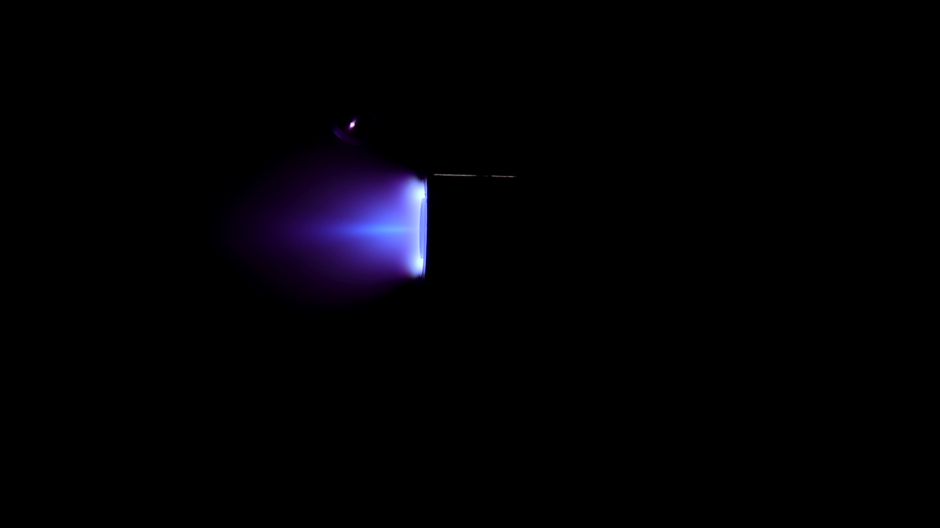
The thruster was unable to operate steadily, and so we were unable to acquire hard data points. Despite this, we can still infer certain aspects of its performance. Based on prior magnetic field tests, the magnetic field is lopsided, resulting in a non ideal field topology, since for optimum performance, the field should be mostly radial. This directly resulted in the plume being quite divergent, as shown in Figure 1, likely causing many ions to have significant non-axial components in their velocities and not contributing to the overall thrust of the engine. It can also be seen that the plasma appears very dense close to the exit plane of the thruster, indicating that most of the ionisation and acceleration is occurring closer to the exit plane, which could explain instabilities and poor performance.
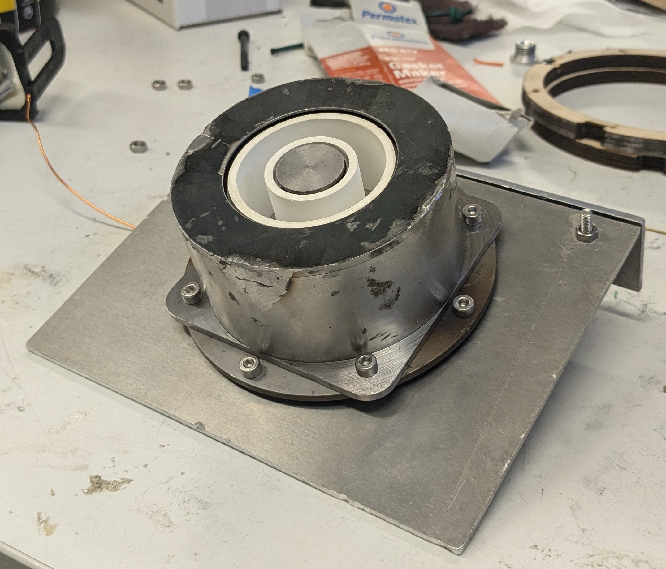
Figure 2, shows Io-1 after its test firing. Damage and wear is present, but expected with the problems it faced.
Io-2
Io-2 is the natural successor of Io-1 and builds directly from its legacy. Io-2 is a 1kW Argon Hall-effect thruster, with an attempt at magnetic sheilding to extend the lifetime of the thruster. The intial design parameters of IO-2 is shown in Table 1, which ultimatly dictated many subsequent design decisions.
| Parameter | Value |
|---|---|
| Nominal Discharge Power | 1000W |
| Nominal Discharge Voltage | 300V |
| Propellant | Argon |
| Project Budget | £1600 |

A process of research, simulations and iterations of the design lead us to the final design outcome, shown in Figure 3. Io-2 was modelled in SOLIDWORKS and simulated in FEMM and COMSOL in order to find the magnetic, fluid and thermal distributions. Examples of these simulations are found in Figures 4, 5, and 6.

Unfortunately, while inital simulations predicted that IO-2 would be magnetically shielded, Figure 4 shows otherwise. This was a result of errors in our initial simulatiosn, and Figure 4 is the updated simulation after manufacturing began. The reason it wasn't shielded was due to the peak field being located outside the dishcarge channel. To make Io-2 magnetically shielded, the magnetic screen walls could be raised higher, which would force the field to curve round the discharge channel. Additionally, to bring the peak field inside the channel and improve magnetic sheilding, more advanced materials with higher saturating H-B curves would be needed, or a more creative design. This error does not mean the thruster will not run, but will mean it will be susceptible to higher erotion on the channel.


As manufacturing is underway, some short updates to this page will take place and to the report published below!
Io-2's design process, simulations, equations used, and more, are all documented and published by SUEP. This report is available for free to download below, in order to help others learn from our mistakes and improve their own and our designs. We hope this report and others produced by SUEP, inspires and advances the electric propulsion field!
Hall Effect Thruster Database
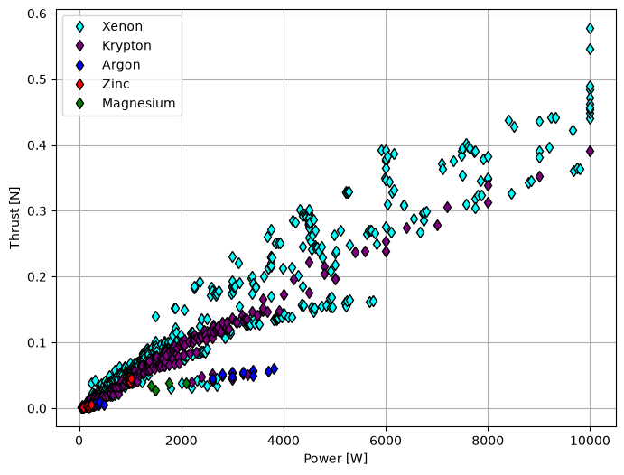
Before working on the Zeus project, the SUEP team created a database of current and past Hall-effect thruster parameters and their performances. These parameters and performances are outlines in Table 2. We want to extend our database of information to anyone interested, which has allowed us to define key design parameters for our Zeus project. For example, Figure 7 shows how the database has been used to compare parameters such as thrust, and power to different HET fuel types. References to where the data was gathered has been provided within the database.
Please note that the information we have gathered was openly available online and we have provided references for each source. SUEP wishes to abide by any copyright laws, so please contact us if any data is yours and wish for it to be removed!
| Parameters | Symbols | Definitions |
|---|---|---|
| Mean Channel Diameter | d | The mid circle between the outside and inside diameter circles |
| Channel Width | h | The distance between the inside and outside diameters of the channel |
| Channel Length | L | The distance from the top of the anode to the exit plane of the thruster |
| Power | p | Total discharge power from the anode |
| Discharge Voltage | Ud | Total discharge voltage from the anode |
| Anode Mass Flow Rate | ṁ | Total anode mass flow rate input |
| Total Thrust | Thrust | Total thrust Produced |
| Specific Impulse | Isp | Fuel efficiency |
| Type of HET (e.g SPT, TAL) | Type | Configuration of hall thruster, can dramatically effect performance very important to not list incorrectly |
| Ionization Energy | Φ | The amount of energy taken to ionize one atom into a +1 ion |
| Atomic Mass | M | The mass of one atom of the propellant |
Zeus
Zeus is SUEP's most recent project, with the aim of being one of the first undergraduate student societies to create a Zinc solid fuel Hall-effect thruster. More updates are to happen soon!